Recently, a coworker described a problem which caused me to search for an unsolicited solution. At the company I work for we deal with many large steel poles. These are fabricated with either a large base plate designed to mate to a group of anchor bolts or they are welded with a flat bearing plate designed to be buried & backfilled.
The style of pole designed to be buried (directly embedded), are usually coated with a polyurethane or equivalent coating. This coating’s purpose is primarily to prevent excessive corrosion. The appearance is that of black tar & becomes very tough with strong abrasion resistance.
These coatings, along with any other paint/enamel/powder, requires the surfaces it has to adhere to – cleaned. The surfaces of these poles come from the mill with .. well mill scale. The mill scale and other oils on the surface of these poles is bead blasted away & requires prompt coating. If you live in a climate which has water falling from the sky as often as it does here in the PNW, you’ll have short intermittent periods to paint.
The problem I’m alluring to is a very simple one. How do you support a pole while it is being blasted/painted & allow it to be rotated. The current method utilizes rollers. Along with with 1 or 2 basic passive rollers there is a powered roller to prevent manual interaction while coating. If we utilized an additional roller under the coated end of the pole shaft, the rollers would screw up the coating. If we removed the support completely on the coated region of the pole, it would tip. The coated region is always the thicker end of a tapered shaft, so the center of gravity is often near or in the cantilevered portion of the poles.
The obvious solution is to put a 3″ hole in the bearing plate. We’ll build a stand with a 2 1/2″ STD pipe (2 7/8″ outer diameter). After coating, the hole can be patched with a bolted-on identification plate which should be supplied either way.
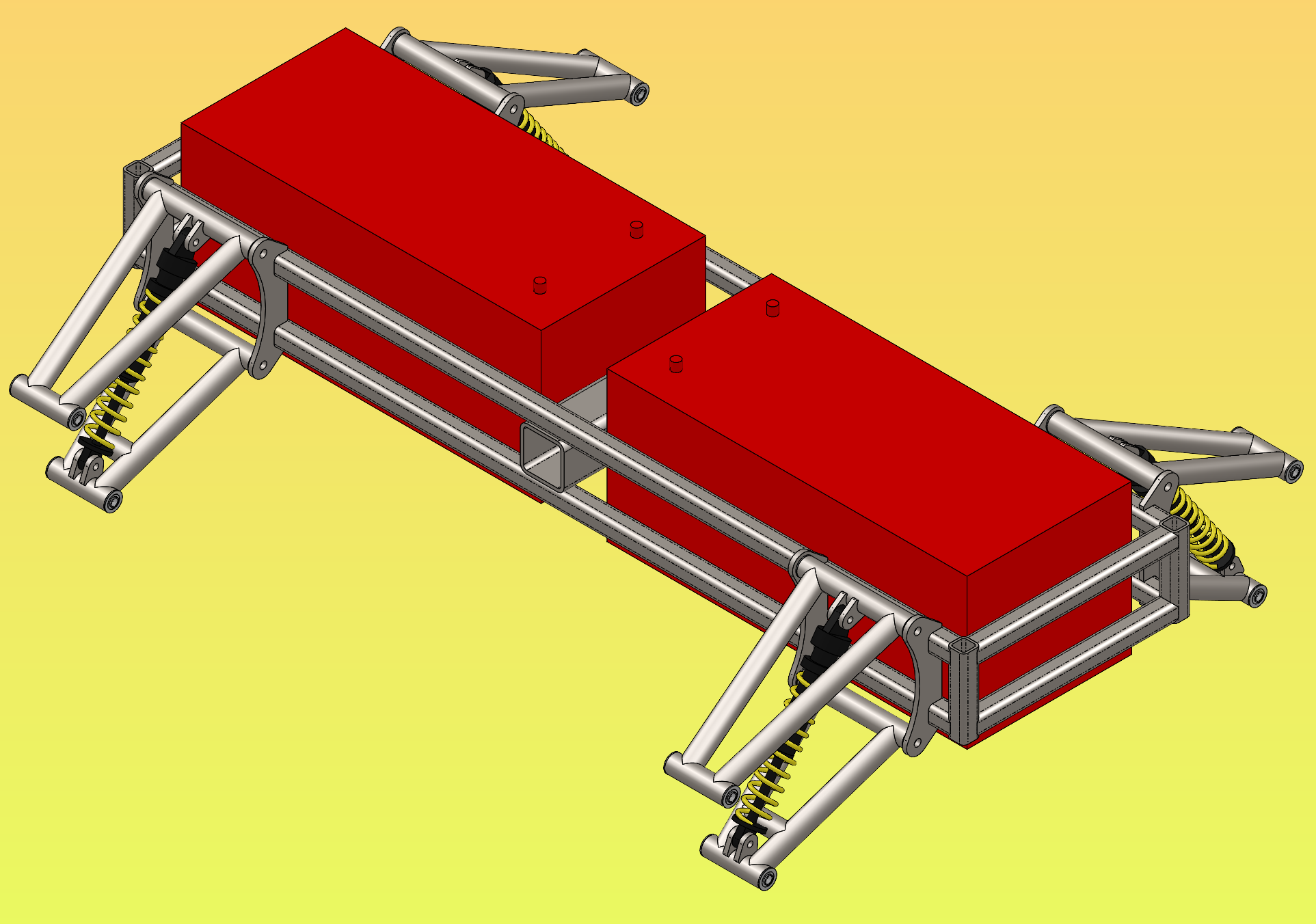
The obvious solution is boring. So I took it upon myself to draft possible solutions with over complicated designs. These are those designs.
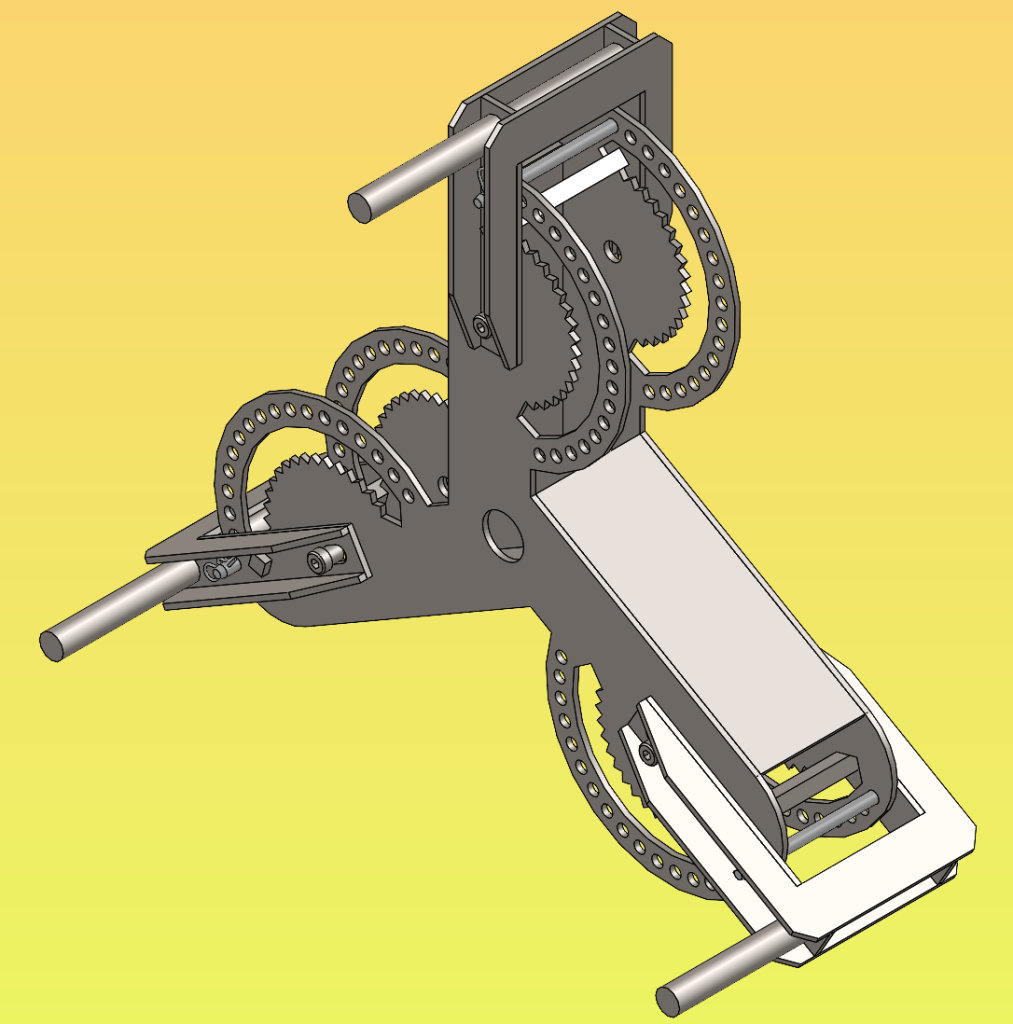
My first design was inspired by the machining world. What I need is essentially a 3-jaw chuck, which is commonly used on lathes and machining jigs. The general concept is to utilize 3 arms which slide, rotate, and pin into predefined locations. This doesn’t allow for the fine adjustment required to put outward or inward pressure to securely support a shaft. An assembly on each of the 3 pins would be required, but by the time I was about to model those – my motivation died. I took my screenshot and called it a day. I don’t like it. To me, this is a doodle. Enjoy my doodle.
Second day.
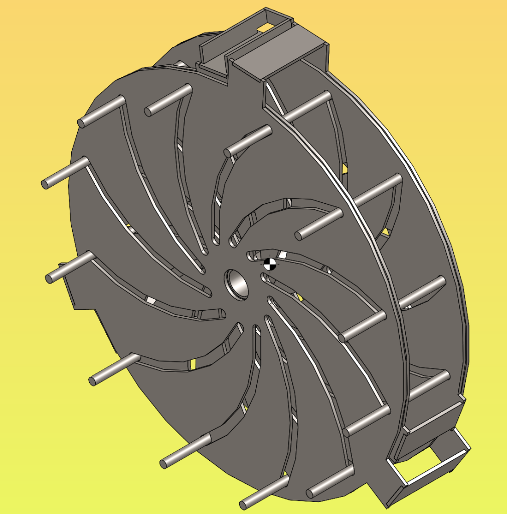
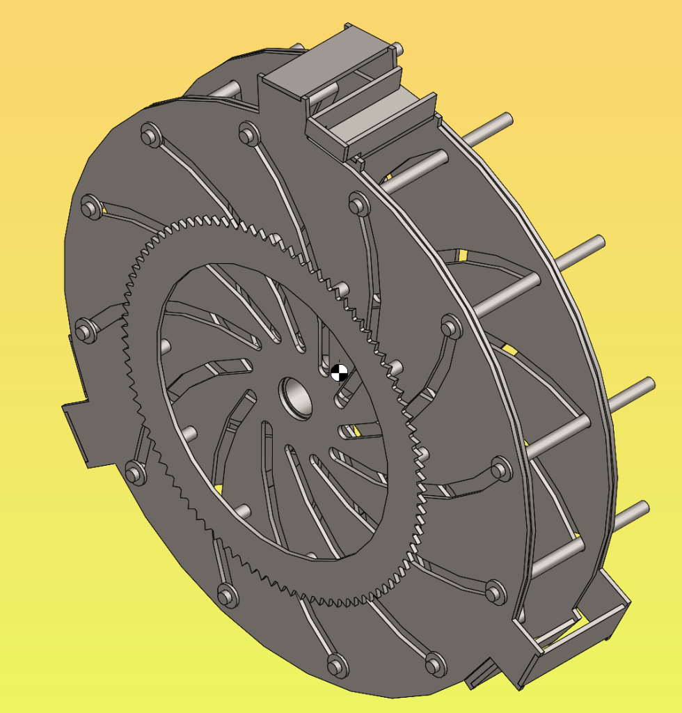
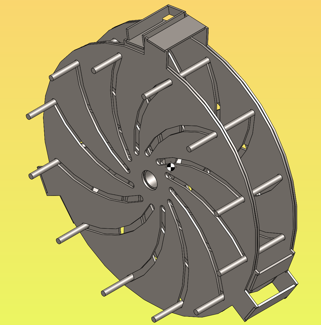
My second design had to solve my first design’s biggest flaw. The flaw of limited positions. The design above allows infinite adjustment between the ends of the range. I forced myself to spend the same amount of time on this design. So the part you are missing is the hand crank located on the inner weldment which would rotate the outer weldment with the big cog shown.
This assembly weighs 770lbs and has a range of 12″ to 48″. It’s both too heavy to handle and not large enough to accommodate all of our poles. It was a fun challenge, but it will lie here – never to be birthed.
