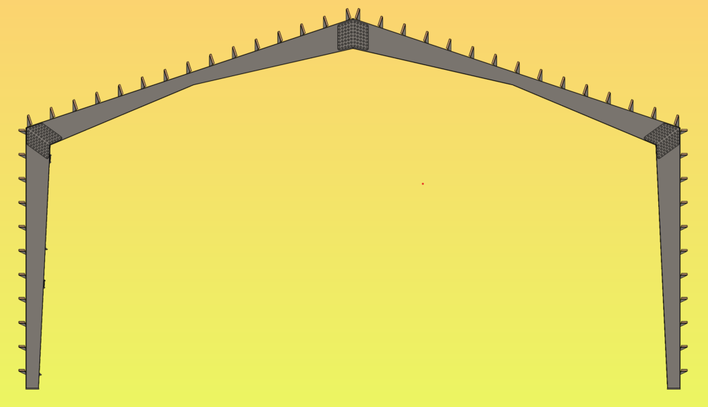
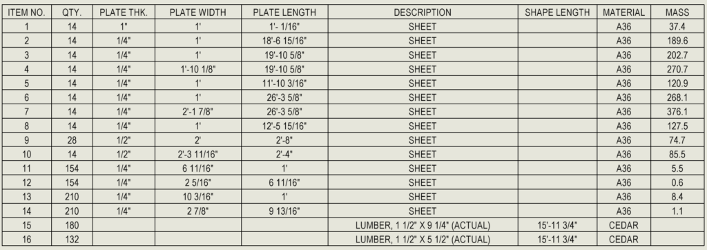
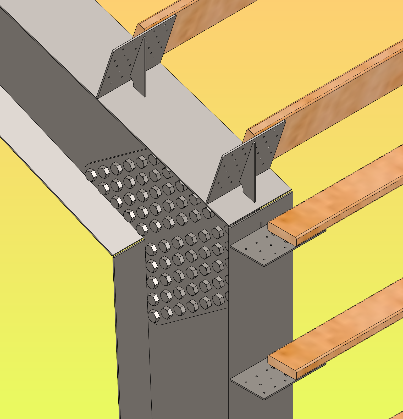
I did something! I couldn’t make another post without fixing the primary complaint in my previous post. The corner connections have gone from flange to sandwich plates. This may not be the technical term, but I’m hungry and I like the visual. The splice plates now rely on roughly too many bolts in shear. This is nothing but conceptual. I am no engineer, and I don’t want to be. The intent of this is to generate a starting point for calculations. Though it might be fun to run a static FEA to see the pretty colors.

Technical Mumbo Jumbo Alert
My main focus on this project has been about how I model, rather than what. I have been modeling using parametric software for over a decade now. I rarely model using multi-body part files. I have been to habituated to assembly files. In the professional D&E world, the methodology of drafting or design is often heavily by the ERP/MRP/PLM systems the company has implemented. My places of work are no different.
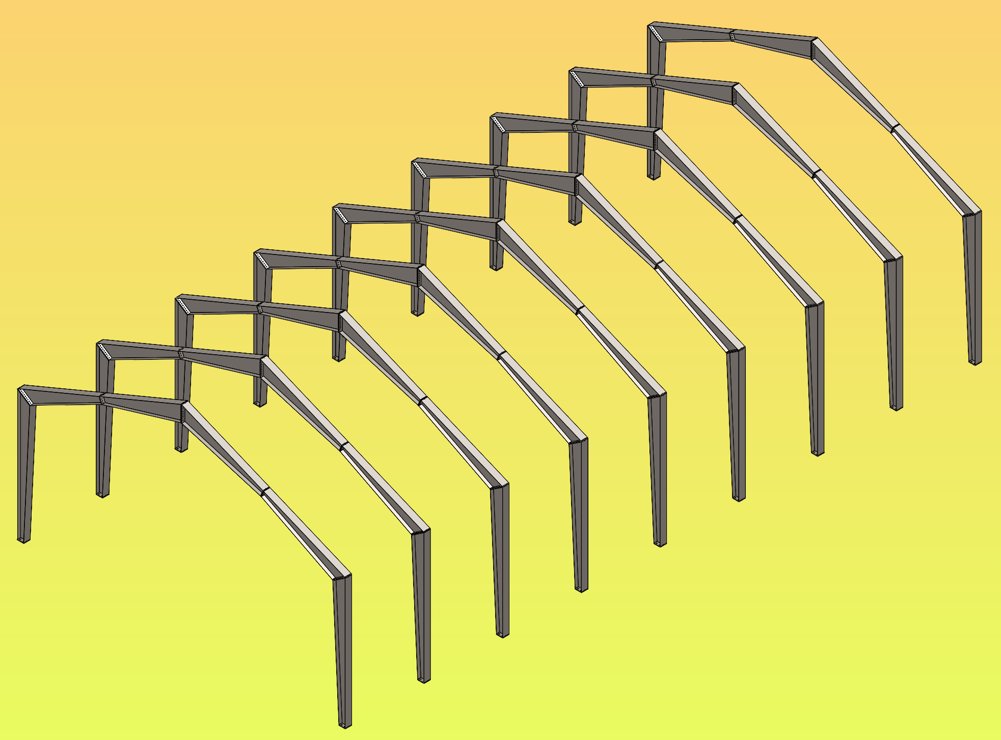
This is a multi-body part. Due to my professional restrictions, this part file is analogous to stretching my creative legs. It is not for nothing.

To be continued.

